PULS
24 V dc UPS for external battery 3.9-130 Ah
The UB20.241 uninterruptible power supply controller (DC-UPS) is used in addition with a 24V power supply and batteries to bridge power failures or voltage fluctuations. This configuration can prevent expensive downtimes, long restart cycles and loss of data.
A unique feature of the UB20 series is the constant voltage in battery mode, which will not change as the batteries discharge. The buffer voltage in battery mode can be set to four different output values. Another feature is the utilization of two independent battery chargers for the two 12V-batteries in series. This feature makes matching batteries unnecessary and allows for precise battery charging, testing and optimized usage of the battery capacity to achieve the longest battery service life.
The UB20.241 includes many battery diagnostic functions that ensure a reliable operation of the entire system. Furthermore, a temperature controlled charging
extends the life of the batteries. It also includes a selectable buffer time limiter as well as ready, buffering and replace battery contacts. For safety and
maintenance, an inhibit input signal is included which prevents a battery backup.
Technical Data
Input/Output | ||
Input voltage from the unit | 24 V DC (23.3-30 V DC continuous operation) | |
Input voltage from the battery | 2x12 V DC two batteries in series | |
Output voltage during normal operation | 0.15 V DC lower than the input voltage from the power supply | |
Output voltage in battery mode | Selectable via switches in the front. 22.5, 24, 25 or 26 VDC. | |
Output current during normal operation via the unit (max.) | 25 A. If feeding unit is greater than 28 A, a 25 A fuse between the unit and the control unit is installed. | |
Output current in battery mode (max.) | 20 A (30 A for 4s, then the output is set in the "hick-up" mode) | |
Input current internal consumption type | 70 mA | |
Input current when charging from supply 24 V DC | 1.7 A battery switch in position <10 Ah 3.4 A battery switch in position >10 Ah | |
*The total input power when the battery is charging | 1.77 A or 3.47 A | |
| ||
Permitted battery sizes | 3.9-130 Ah | |
Charging the battery type | 1.5 A battery switch in position <10 Ah 3 A battery switch in position >10 Ah | |
Charging type | Ex. 8 hours 12 Ah completely discharged battery | |
Voltage level of the connection of the battery | Identical to the selected output voltage in battery | |
Selectable buffer times | 10 s, 30 s, 1 m, 3 m, 10 m alt. endlessly until deep discharge protection becomes | |
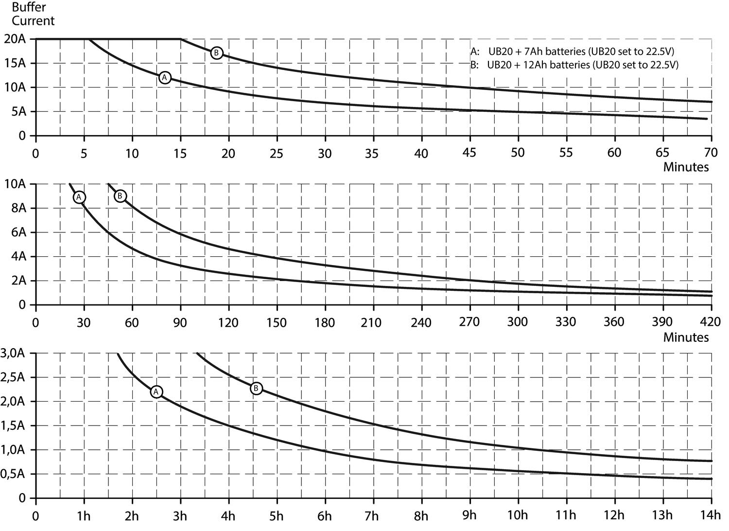
Buffer with 2x7 Ah battery ** | Min. 13.3 min at 10 A. Typ. 16.53 min at 10 A | |
Min. 4 min at 20 A. Typ. 5.12 min at 20 A | ||
Buffer with 2x12 Ah battery ** | Min. 35.3 min at 10 A. Typ. 44.3 min at 10 A | |
Min. 11.53 min at 20 A. Typ. 14.51 min at 20 A | ||
External temp. | PT-1000. See the "Wiring" tab. | |
Power loss type | 3.7 W Supply via power supply, 20 A load current and the battery is fully charged. | |
| ||
| 22.7 W. Supply via battery, 20 A load current | |
Operating temperature controller | -40 to +70 °C (some power reduction over +60 °C). | |
Connection power | Screw connection. 2.5-4 mm² multifilament, 2.5-6 mm² monofilament | |
Connection signal contacts | Connector terminals. 0.2-1.5 mm² | |
Weight | 700 g | |
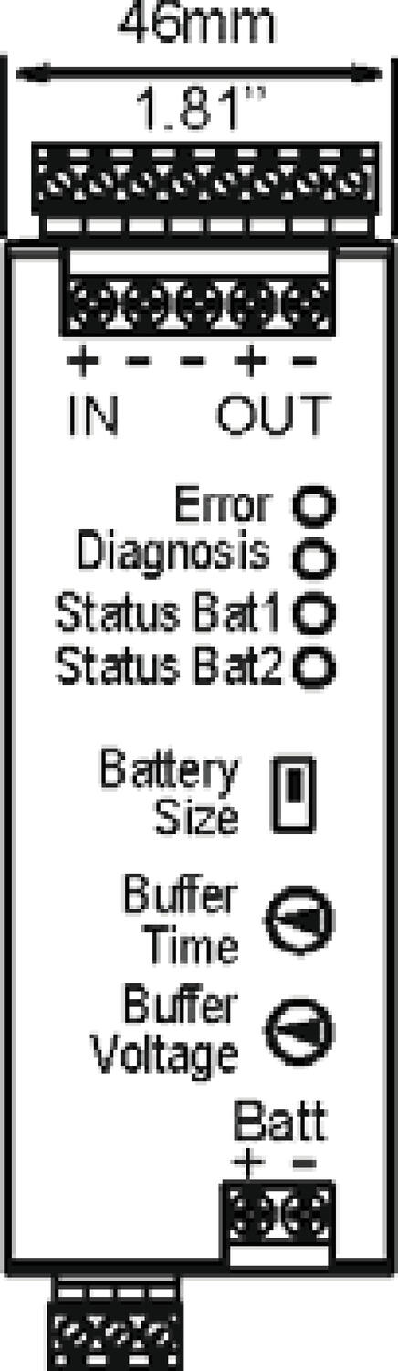
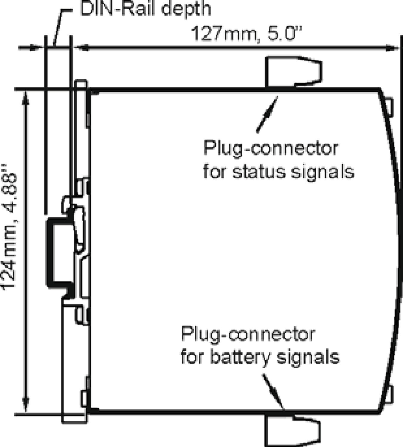
Dimensions WxHxD (mm) | 46x124x127. (Supplement for signal contacts in height and DIN rail length) | |
Signal contacts | Ready. Controller ready for backup. | |
| Buffering. Control of backup / battery mode. | |
| Repl. Bat. Battery replacement | |
Input inhibit | External shutdown by 24 V DC. Min. pulse time 250ms. Max 35 V DC. | |
MTBF enl. SN 29500, IEC 61709, 20 A and 40 °C | 649 000 hours (Operation with power supply) | |
Approvals | CE, UL508 Listed, UL 60950-1, CB-Scheme | |
EMC | EN 61000-6-1, EN 61000-6-2, EN 61000-6-3, EN 61000-6-4. | |
Compliant standards | EN/ IEC 60204-1, EN/IEC 61131-2, EN50178, IEC 62103 | |
* The total input power must be deducted from the unit's rated current, the result is the maximum available load current. Ex. 20 A units is the maximum load current 16.53 A with battery> 10 Ah. 3.47 A is used for internal consumption and charging of the batteries.
** The minimum value of 20% include the aging of the battery and a cable length of 1.5 meters with the area 4 mm² between battery and controller.
Backup times
Discharge curve |
|

Dimensions & wiring
Dimensions | |
|
|


Wiring | |
| |
| |
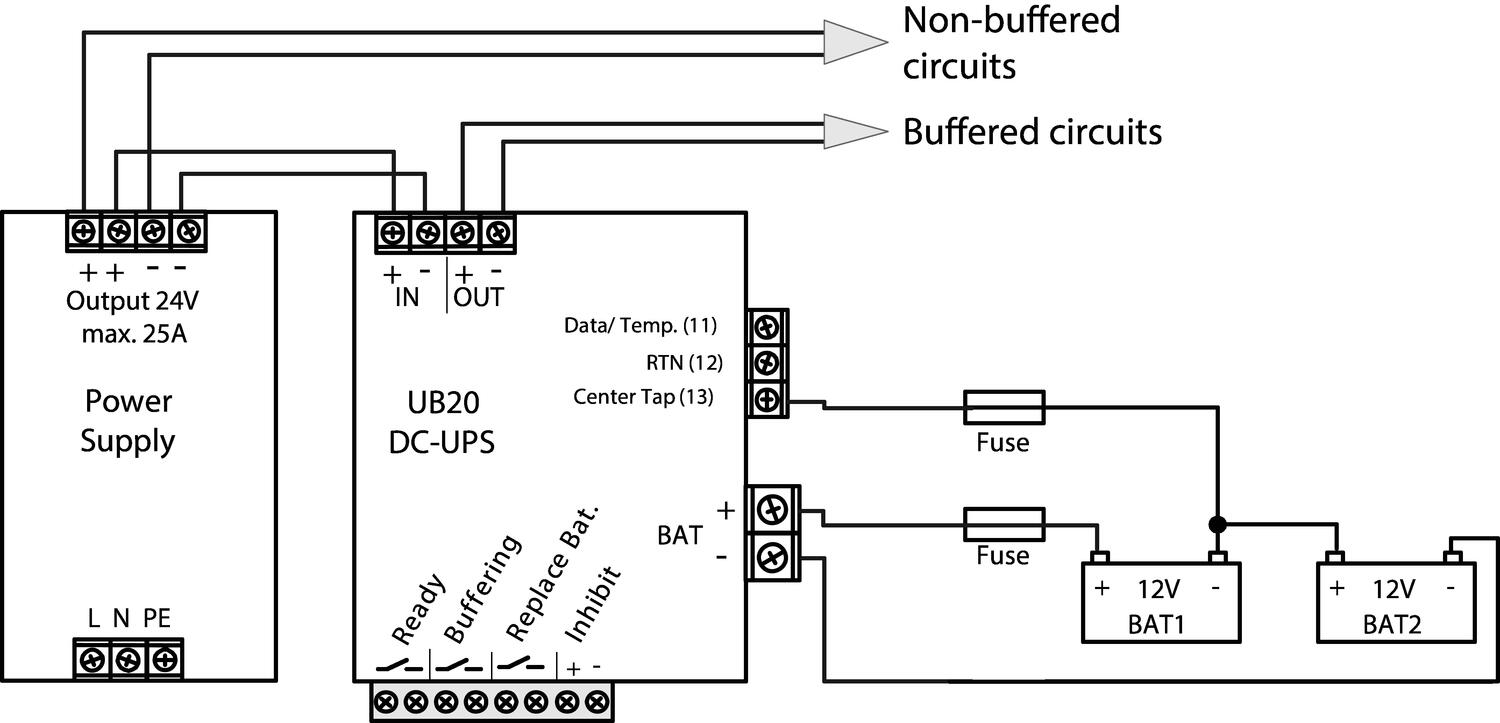
Connecting the center tap of the treatment of the batteries separately | |
| |
For optimized charging and longevity required that each battery is controlled separately. We recommend connecting the midpoint of the batteries with a center drain connection on the controller to achieve maximum performance. Install a 4 A fuse between the battery and the controller. | |
| |
Connection of a complete DC UPS systems | |
| |
| |
Ventilation | |
Install the battery so that it does not get heated by adjacent equipment and ensure that there is proper ventilation according EN50272-2. | |


Part Numbers
Order number | Description |
UB20.241 | DC-UPS module for battery. 24 V DC/20 A |
UZO24.071 | Battery holder for DIN rail. For battery 7 Ah |
UZO24.121 | Battery holder for DIN rail. For 2x12 Ah batteries |
- Load current 20 A
- Control of each individual battery
- Selectable output voltage in battery mode
- Temperature compensated charging
- Relay outputs for status


Selected variant
DC UPS 24V dc I/P 24V dc 20A O/P 3.9-150Ah
Art:
Selected variant
Specifications
| Approvals | ABS, CB, CE, CSA, CSA US, EX, GL, IECEx, UL |
|---|---|
| Charging The Battery Type | 3 |
| Depth | 117 |
| Efficiency | 99 |
| Height | 124 |
| Input Current During Charging Of Aggregates | 3.4 |
| Input voltage for battery connection | 22.8 |
| Input Voltage From battery | 24 |
| Input Voltage From The Unit | 24 |
| IP Class | IP20 |
| Life span | 122 000 h @ 20 A, 40 °C |
| MTBF (IEC 61709) | 649 000 h @ 20 A, 40 °C |
| Output current at 24 V dc | 20 |
| Output Current During Normal Operation Via The Unit Max | 25 |
|---|---|
| Output current for battery operation max | 20 A (30 A @ 4 s) |
| Output Voltage at Battery | 22.5 |
| Output Voltage Normal Operation | 24 |
| Permitted Battery Sizes | 3,9-150 Ah |
| Power Reduction Of 60 To 70 ° C | 12 |
| Ripple. max | 120 |
| Temperature Range Without Derating From | -40 |
| Temperature Range Without Derating To | 60 |
| Voltage Level Of The Connection Of The Battery | 24 |
| Weight | 0.7 |
| Width | 49 |


Product description
The UB20.241 uninterruptible power supply controller (DC-UPS) is used in addition with a 24V power supply and batteries to bridge power failures or voltage fluctuations. This configuration can prevent expensive downtimes, long restart cycles and loss of data.
A unique feature of the UB20 series is the constant voltage in battery mode, which will not change as the batteries discharge. The buffer voltage in battery mode can be set to four different output values. Another feature is the utilization of two independent battery chargers for the two 12V-batteries in series. This feature makes matching batteries unnecessary and allows for precise battery charging, testing and optimized usage of the battery capacity to achieve the longest battery service life.
The UB20.241 includes many battery diagnostic functions that ensure a reliable operation of the entire system. Furthermore, a temperature controlled charging
extends the life of the batteries. It also includes a selectable buffer time limiter as well as ready, buffering and replace battery contacts. For safety and
maintenance, an inhibit input signal is included which prevents a battery backup.
Technical Data
Input/Output | ||
Input voltage from the unit | 24 V DC (23.3-30 V DC continuous operation) | |
Input voltage from the battery | 2x12 V DC two batteries in series | |
Output voltage during normal operation | 0.15 V DC lower than the input voltage from the power supply | |
Output voltage in battery mode | Selectable via switches in the front. 22.5, 24, 25 or 26 VDC. | |
Output current during normal operation via the unit (max.) | 25 A. If feeding unit is greater than 28 A, a 25 A fuse between the unit and the control unit is installed. | |
Output current in battery mode (max.) | 20 A (30 A for 4s, then the output is set in the "hick-up" mode) | |
Input current internal consumption type | 70 mA | |
Input current when charging from supply 24 V DC | 1.7 A battery switch in position <10 Ah 3.4 A battery switch in position >10 Ah | |
*The total input power when the battery is charging | 1.77 A or 3.47 A | |
| ||
Permitted battery sizes | 3.9-130 Ah | |
Charging the battery type | 1.5 A battery switch in position <10 Ah 3 A battery switch in position >10 Ah | |
Charging type | Ex. 8 hours 12 Ah completely discharged battery | |
Voltage level of the connection of the battery | Identical to the selected output voltage in battery | |
Selectable buffer times | 10 s, 30 s, 1 m, 3 m, 10 m alt. endlessly until deep discharge protection becomes | |
Buffer with 2x7 Ah battery ** | Min. 13.3 min at 10 A. Typ. 16.53 min at 10 A | |
Min. 4 min at 20 A. Typ. 5.12 min at 20 A | ||
Buffer with 2x12 Ah battery ** | Min. 35.3 min at 10 A. Typ. 44.3 min at 10 A | |
Min. 11.53 min at 20 A. Typ. 14.51 min at 20 A | ||
External temp. | PT-1000. See the "Wiring" tab. | |
Power loss type | 3.7 W Supply via power supply, 20 A load current and the battery is fully charged. | |
| ||
| 22.7 W. Supply via battery, 20 A load current | |
Operating temperature controller | -40 to +70 °C (some power reduction over +60 °C). | |
Connection power | Screw connection. 2.5-4 mm² multifilament, 2.5-6 mm² monofilament | |
Connection signal contacts | Connector terminals. 0.2-1.5 mm² | |
Weight | 700 g | |
Dimensions WxHxD (mm) | 46x124x127. (Supplement for signal contacts in height and DIN rail length) | |
Signal contacts | Ready. Controller ready for backup. | |
| Buffering. Control of backup / battery mode. | |
| Repl. Bat. Battery replacement | |
Input inhibit | External shutdown by 24 V DC. Min. pulse time 250ms. Max 35 V DC. | |
MTBF enl. SN 29500, IEC 61709, 20 A and 40 °C | 649 000 hours (Operation with power supply) | |
Approvals | CE, UL508 Listed, UL 60950-1, CB-Scheme | |
EMC | EN 61000-6-1, EN 61000-6-2, EN 61000-6-3, EN 61000-6-4. | |
Compliant standards | EN/ IEC 60204-1, EN/IEC 61131-2, EN50178, IEC 62103 | |
* The total input power must be deducted from the unit's rated current, the result is the maximum available load current. Ex. 20 A units is the maximum load current 16.53 A with battery> 10 Ah. 3.47 A is used for internal consumption and charging of the batteries.
** The minimum value of 20% include the aging of the battery and a cable length of 1.5 meters with the area 4 mm² between battery and controller.
Backup times
Discharge curve |
|
Dimensions & wiring
Dimensions | |
|
|
Wiring | |
| |
| |
Connecting the center tap of the treatment of the batteries separately | |
| |
For optimized charging and longevity required that each battery is controlled separately. We recommend connecting the midpoint of the batteries with a center drain connection on the controller to achieve maximum performance. Install a 4 A fuse between the battery and the controller. | |
| |
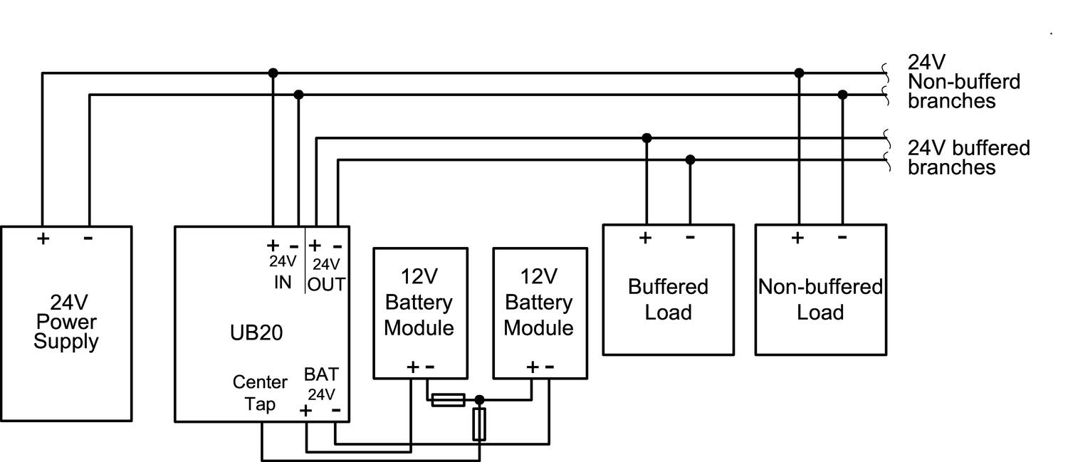
Connection of a complete DC UPS systems | |
| |
| |
Ventilation | |
Install the battery so that it does not get heated by adjacent equipment and ensure that there is proper ventilation according EN50272-2. | |
Part Numbers
Order number | Description |
UB20.241 | DC-UPS module for battery. 24 V DC/20 A |
UZO24.071 | Battery holder for DIN rail. For battery 7 Ah |
UZO24.121 | Battery holder for DIN rail. For 2x12 Ah batteries |
Add product as a new cart row
You already added this product. Choose whether to increase quantity on the existing row or add the product as a new row.

F-Gas Regulation & Enclosure Cooling in Ireland
Modular busbar systems that streamline power distribution, improve safety, and speed up panel builds.

Welcome Jim Murray to OEM Demesne
A familiar face returns. Jim Murray joins OEM-Demesne as Chief Sales & Supplier Officer, bringing 26 years of industry leadership back to the business at a defining moment in the move to OEM Automatic.

Katko IsoSafe KSM Safety Switch
Katko has launched a significant upgrade to its IsoSafe KSM safety switch range (16–25A), built around the realities of modern installation work. The redesigned side-operated switch combines an
.png?as=1&iar=0&hash=32754F69BDE594727B35F2B8B9C1A3EC)
Wohner 60 Classic and Crossboard
Modular busbar systems that streamline power distribution, improve safety, and speed up panel builds.

Tekox Terminal Strips Safety Blocks and Porcelain Blocks
Great electrical installations don't fail because of the major components. They fail because of the small ones that didn't get enough attention.
It's easy to focus on the big-ticket items during specification — and let the terminal blocks become an afterthought. But inferior connection components have a habit of making themselves known over time. Loose connections, degraded insulation, premature failure. The kind of faults that are frustrating to trace and expensive to fix.
Tekox engineer their terminal strips, safety blocks, insulated strips, and porcelain blocks to the standards your installations deserve. Available now from Demesne Electrical — get in touch and we'll show you the range.

Conta-Clip Push-in PPVK Distribution Terminals
Conta-Clip PPVK push-in potential distribution terminals simplify control cabinet wiring with tool-free connections, compact DIN rail mounting, and reliable current distribution up to 41A.


